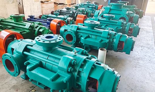
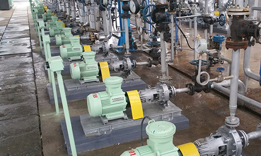
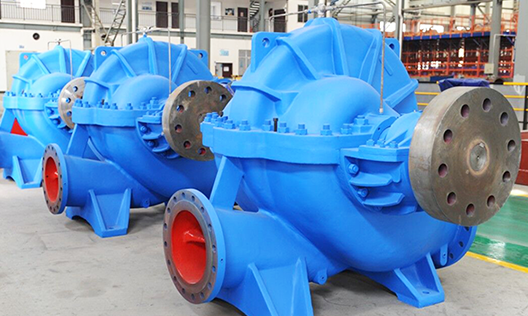
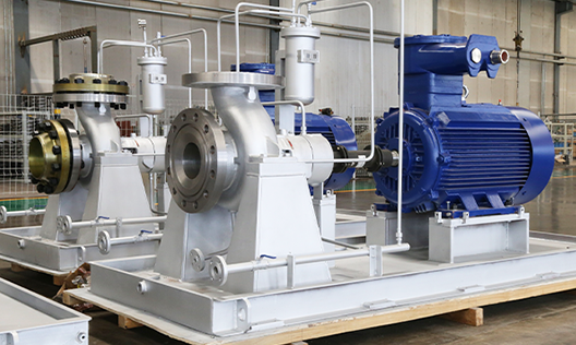
(Left) K type mechanical sealing (Right) K type mechanical sealing with cooling water 
Applications of the corrosion and wear-resistant mortar pump type UHB
1. The UHB-ZK chemical mortar pump is used in the phosphate fertilizer industry: transport of diluted acids, mother liquor, wastewater, seawater, fluorosilicic acid with silica, phosphoric acid slurry, and other media.
2. The UHB-ZK chemical mortar pump is used in the metallurgy of non-ferrous metals: especially suitable for transporting various acids, corrosive slurries, slurries (for filter presses), electrolytes, and wastewater in the wet metallurgy of lead, zinc, gold, silver, copper, manganese, cobalt, rare earths, etc.
3. The corrosion-resistant UHB-ZK mortar pump is used in the chemical industry and other enterprises: for clear liquids or slurries of various sulfuric acids, hydrochloric acids, alkalis, and oils. Production of titanium dioxide, red iron oxide, various dyes and pigments, processing of non-metallic minerals, among others.
4. The UHB-ZK mortar pump is used in the chlorine and alkali industry: hydrochloric acid, liquid alkalis, electrolytes, etc.
5. The UHB-ZK type mortar pump is used in water treatment: pure water, ultrapure water, wastewater (wastewater from tanning, electroplating, electronics, paper, textiles, food, domestic, pharmaceuticals, etc.).
6. It is used in steel companies: sulfuric acid and hydrochloric acid in pickling systems, wastewater with impurities.
7. The corrosion-resistant mortar pump is used for the wet desulfurization circulation pump: it can simultaneously adapt to alkaline, acidic, and corrosive positions.
8. It is used for the transport of corrosive liquids and coal slurry in the coal industry and coal chemistry; combined pump for washing and selecting coal.
Starting, operation, and maintenance of the chemical corrosive mortar pump
1. Preparation before operation:
Before the operation test, the coupling or shaft must first be manually turned to check if the rotation direction is correct and if the operation is flexible. If it cannot be turned or there are abnormal noises, it should be inspected in time. During the inspection, first manually check from the outside if the coupling is level, and observe through the oil mirror hole in the bearing support if the lubricant level is close to the center line of the oil mirror (if there is too much, a little should be drained; if there is too little, it should be added). While inspecting, turn the coupling. If the problem persists, the pump should be disassembled for inspection (when disassembling, refer to the structural diagram and disassembly procedure in this manual), clean foreign objects, and contact our factory to agree on a solution.
2. Steps to start:
a. Fill the pump with liquid
b. Open the inlet valve in a timely manner (if the inlet and outlet valves are one-way check valves, no manual operation is required)
c. Connect the power supply
d. Open the purge valve
3. Operation:
If there are abnormal noises during operation or the motor heats up abnormally, the machine should also be stopped for inspection; the method and steps for inspection are the same as in point 1.
4. Steps to stop the machine:
a. First close the valve at the outlet
b. Cut off the power supply and timely close the inlet valve (if the inlet valve is a one-way check valve, no manual operation is required)
5. Maintenance
a. The lubricating oil in the bearing support should be changed periodically, normally once every six months.
b. In cold weather, if there is freezing after stopping the pump, the cooling water should first be connected at the seal; if necessary, hot water can be added to thaw, then manually turn the coupling until it operates flexibly, and then start according to the starting steps.
c. For pumps with a cooling device, the cooling water should be connected before starting; during normal operation of the pump, it can remain connected; if conditions do not allow, it can also be turned off. There are no requirements for the flow and pressure of the cooling water, it can be tap water.
d. The operation of the pump with the outlet valve closed is called the closed pressure operation state. The closed pressure operation time for fully plastic or lined pumps should be as short as possible; for media at room temperature, it should not exceed 5 minutes; for media at high temperature, preferably no more than 2 minutes.
e. For pumps with a split casing, such as pumps with an inlet diameter greater than 50 mm, the sealing plastic on the split surface may change size due to thermal expansion and contraction. When installing, the connection screws of the split surface should be tightened first, then connect the inlet pipe to avoid leaks at the split surface. This rule is especially important for users in the north.
f. The pump cannot support the weight of the inlet and outlet pipes; the inlet pipe should be as short as possible; the vertical distance from the pump outlet to the valve should be as short as possible.
g. Ensure that there are no traces of water in the motor to avoid moisture in the motor.
Disassembly and assembly procedure of the chemical mortar pump
1. Pump without attached impeller (pump with inlet diameter ≤125 mm)
Disassembly order: (refer to the structural diagram in this manual)
a. Loosen the connection bolts between the pump body 5 and the pump cover, disassemble the pump cover
b. Loosen the impeller cover 2 (left thread) and the anti-rotation nut 3 (left thread), disassemble the impeller 4
c. Loosen the connection bolts between the pump body 5 and the bearing support 10, disassemble the pump body 5
d. Loosen the connection bolts between the sealing box 6 and the pump body 5, disassemble the sealing box 6
e. Unscrew the pressure back cover on the sealing box, take out the oil seal
The assembly order is the reverse of the disassembly order, attention should be paid to the following:
After tightening the impeller cover, check the gap between the impeller and the pump body; this gap should be approximately 2 mm.
b. After installing the pump box, check the gap between the pump cover and the impeller (looking from the outlet inward); this gap should be approximately 2 mm; for pumps handling media at high temperatures, this gap should be approximately 2.5 mm.
c. If the gap between the impeller and the pump body does not meet the requirements, it can be adjusted by adding or removing washers between the impeller and the shaft sleeve.
d. If the space between the pump cover and the impeller does not meet the requirements, it can be adjusted by adding or removing washers between the pump body and the pump cover.
2. Pump with attached impeller (pump with inlet diameter >125 mm)
Disassembly order: (see the structural diagram in the manual)
a. Loosen the connection bolts between the pump body 5 and the pump cover 1, disassemble the pump cover 1.
b. Loosen the impeller cover 2 (left thread) and the anti-rotation nut 3 (left thread), disassemble the impeller 4
c. Loosen the connection bolts between the pump body 5 and the bearing support 12, and the connection bolts between the sealing box 7 and the pump body, disassemble the pump body 5.
d. Successively disassemble the attached impeller, the sealing box, the oil seal, and the shaft sleeve.
The assembly order is the reverse of the disassembly order, attention should be paid to the following:
a. After tightening the impeller cover and the nut behind the water retaining ring, check the space between the impeller and the pump body; this space should be approximately 2.5 mm.
b. After installing the pump cover, check the space between the pump cover and the impeller (looking from the outlet inward); this space should be approximately 2 mm; for pumps handling media at high temperatures, this space should be approximately 2.5 mm.
c. If the space between the impeller wheel and the pump body does not meet the requirements, it can be adjusted by adding or reducing gaskets between the impeller and the shaft sleeve.
d. Pump cover: if the space between the cover and the impeller does not meet the requirements, it can be adjusted by adding or reducing gaskets between the pump body and the cover.