

-
Products
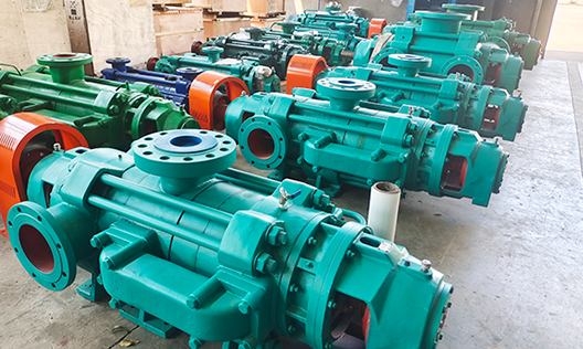
Puede fabricar 26 series de productos, incluyendo bombas de circulación para grandes centrales eléctricas, bombas de condensación para grandes centrales eléctricas, bombas petroquímicas, bombas multietapa, bombas de aguas residuales y lodo, bombas multietapa autoequilibradas, bombas de doble succión y única etapa tipo split, y bombas centrífugas de succión simple y única etapa.
-
Cases
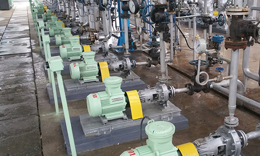
La elección de más de cientos de miles de clientes, cubriendo industrias como minería de carbón, metalurgia, química, energía, recursos hídricos, alimentos, municipalidades y protección ambiental, y exportando a Asia Sudeste, África, América y otros lugares.
-
Service
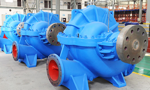
La empresa fue la primera en la industria en obtener las certificaciones internacionales del sistema de calidad ISO 9001:2008, del sistema de gestión ambiental ISO 14001 y del sistema de gestión de seguridad y salud ocupacional GB/T 28001, además de la certificación API 610 de la Asociación Estadounidense del Petróleo.
-
About us
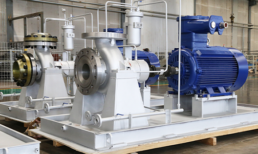
La empresa, fundada en 1989, es una empresa nacional de alta tecnología integral que integra diseño, investigación y desarrollo, fabricación y servicios; actualmente es una empresa clave en la industria china de bombas centrífugas y una de las grandes fábricas especializadas.
-

Blogs
Con productos innovadores, calidad excepcional y servicios integrales, buscamos la verdad y la pragmática, avanzamos con iniciativa, y nos esforzamos por lograr el objetivo de ser "la marca líder en el campo de aplicación de bombas centrífugas en el país"! Raigada en Hunan, orientada a todo el país y hacia el mundo!
Main Causes of Flange Damage in Self-Balancing Multistage Centrifugal Pumps and Corresponding Solutions
Publication Date:
2026-01-02
Author:
Source:


Flange as self-balancing Multistage centrifugal pump The key pressure-bearing components of pipeline connections play a crucial role in sealing the medium and transmitting loads. Their structural integrity directly determines the safety and sealing performance of the pump unit. In industrial settings, failures such as flange damage, deformation, and leakage occur frequently, leading not only to waste of media and environmental pollution but also potentially causing equipment downtime and even safety accidents. In this article, Centrifugal pump Changsha Zhonglian Pump Industry, the manufacturer, will share from a technical perspective the primary causes of flange damage in self-balancing multistage centrifugal pumps, along with corresponding solutions, providing professional guidance for the operation and maintenance of enterprise pump equipment.

Please click on the image to learn about the model specifications and product details of Changsha Zhonglian Pump Industry’s [Self-Balancing Multistage Centrifugal Pumps].
I. The Core Cause of Flange Damage in Self-Balancing Multistage Centrifugal Pumps
1. Non-standard installation practices and the absence of a proper maintenance mechanism: During flange installation, if bolts are not tightened in accordance with the principle of uniform diagonal tightening, or if the torque value exceeds or falls below the specified range, it can lead to an imbalance in the forces acting on the flange surface, causing permanent deformation or damage to the sealing surface. Additionally, some installers fail to clean impurities from the flange sealing surfaces or to replace gaskets as required, which can further exacerbate localized stress concentrations. Moreover, neglecting regular maintenance over the long term—such as failing to inspect bolts for corrosion, promptly addressing wear on the flange surfaces, or replacing aged gaskets—will gradually accumulate hidden risks, ultimately leading to failure.
2. Erosive effects of harsh operating conditions: High humidity and extreme temperatures (high temperatures ≥ 150 ℃ or low temperature ≤ -20 Flanges are subject to multiple forms of corrosion when exposed to high-temperature environments (e.g., above 100°C), corrosive media (such as acidic and alkaline solutions, chlorine-containing media, and chemical slurries), and other harsh conditions. High humidity easily leads to rusting of the flange body and bolts, thereby weakening the structural integrity. Sudden temperature changes can cause uneven thermal expansion and contraction in the flange, resulting in thermal stress cracks. Corrosive media can seep through sealing gaps, causing pitting on the flange surface and stress-corrosion cracking—especially in applications such as chemical processing, metallurgy, and wastewater treatment, where the rate of damage is significantly accelerated.
3. Insufficient Material Selection and Operational Condition Compatibility: The corrosion resistance, strength, and temperature compatibility of flange materials directly affect their service life. If ordinary carbon steel flanges are used in corrosive media environments, or low-strength-grade flanges (such as... PN1.0 ) For high-pressure applications (design pressure ≥ 1.6MPa ), premature damage may occur due to material properties failing to meet operational requirements. In some cases, enterprises use flanges made from low-quality recycled materials, which exhibit poor material uniformity and exceed the permissible levels of impurities, thereby reducing the structural load-bearing capacity and making them prone to fractures and deformations.
4. Load Overlimit Caused by Fluctuations in Operating Parameters: When the actual operating pressure of the pump unit exceeds the flange’s rated pressure capacity, or when the flow rate fluctuates dramatically and frequently (e.g., frequent valve starts and stops, sudden changes in system resistance), the fluid impact force within the pipeline will surge sharply. As a result, the flange is subjected to alternating loads over an extended period, leading to fatigue damage. Moreover, if the pump unit’s vibration levels exceed the allowable limits and are not addressed promptly, the vibrational energy will be transmitted to the flange connections, exacerbating bolt loosening and flange surface wear, thereby indirectly triggering further damage.
5. The flange structural design has inherent defects: During the design phase, some flange products fail to fully account for operating conditions—for example, insufficient flange thickness, uneven distribution of bolt holes, unreasonable sealing surface configurations (such as using smooth-surface flanges in high-pressure applications), or excessively small transition fillets—leading to stress concentration. Moreover, if there is a significant difference in thermal expansion coefficients between the flange and the pipe material, the flange is prone to developing additional stresses during operation due to asynchronous thermal expansion and contraction. Over time, these stresses can cause cracks or deformation.
II. A Scientific Response Plan for the Failure of Flanges in Self-Balancing Multistage Centrifugal Pumps
1. Standardize the installation process and establish a regular maintenance mechanism:
Installation Phase: Develop standardized installation operating procedures and require operators to use torque wrenches (accuracy ± 5% ) Divide in diagonal order 3-4 Tighten the bolts evenly in sequence, and strictly adhere to the torque values specified according to the flange material and pressure rating requirements (e.g., carbon steel flanges). PN1.6MPa Corresponding torque value 25-35N ・ m ); Before installation, thoroughly clean the flange sealing surfaces of any oil, dirt, or impurities. Select a gasket that matches the operating conditions (e.g., metal-wound gaskets for high-temperature applications, PTFE gaskets for corrosive media) to ensure tight contact between the sealing surfaces.
Maintenance Phase: Conduct a comprehensive inspection of flanges every quarter, checking for bolt corrosion and the degree of wear on sealing surfaces (scratch depth ≤). 0.2mm Can be sanded and repaired; if it exceeds the standard, it must be replaced), replace annually. 1 Secondary sealing gasket; for flanges exposed to outdoor or humid environments, apply an anti-rust coating (such as epoxy zinc-rich paint), and install corrosion-resistant caps on the bolts to prevent rusting.
2. Optimize operating conditions and strengthen protective measures:
For high-humidity and corrosive environments, install protective covers (such as transparent polycarbonate covers) on flanges to prevent direct erosion by the medium. Additionally, apply anti-corrosion coatings to the flange surfaces (such as... PTFE Coatings, ceramic coatings, or lined flanges (such as PTFE-lined or rubber-lined flanges) can be selected to enhance corrosion resistance.
Under high-temperature operating conditions, install insulation layers on flanges and pipelines to prevent sudden temperature changes. In low-temperature environments, select flanges made of low-temperature tough materials (such as low-temperature carbon steel or stainless steel) to prevent brittle fracture. Optimize the media pretreatment process to reduce the concentration of corrosive media and minimize erosion of the flanges.
3. Scientifically select and match equipment to meet operational requirements:
Select flanges based on actual operating conditions (pressure, temperature, and medium properties): High-pressure operating conditions ( PN ≥ 1.6MPa ) Use welded flanges with necks to enhance structural strength; suitable for environments with corrosive media. 304/316L Corrosion-resistant materials such as stainless steel and Hastelloy; high-temperature operating conditions (≥ 200 ℃) Use high-temperature-resistant alloy flanges to ensure stable material performance.
When making purchases, select products from qualified, reputable manufacturers and verify the material quality documentation (such as material certificates and non-destructive testing reports) to avoid using substandard or non-standard flanges. For flanges used in critical operating conditions, consider conducting third-party inspections (such as hardness tests and non-destructive testing) to ensure that they meet quality standards.
4. Stable operating parameters and control of load impacts:
Install pressure transmitters and flow monitors at the pump unit’s outlet to monitor operating parameters in real time. Set up overpressure alarms and automatic shutdown functions to prevent the pressure from exceeding the flange’s rated pressure capacity. Optimize the piping system design by installing buffer tanks and vibration dampers to reduce fluid hammer caused by flow fluctuations. Regularly perform vibration inspections on the pump unit (amplitude ≤ 0.08mm ), promptly address vibration sources such as bearing wear and impeller imbalance.
Avoid frequent starting and stopping of pump units; when switching operating conditions, adopt a gradual adjustment approach (e.g., slowly adjusting valve openings) to reduce the impact of sudden load changes on flanges. For long-distance pipelines, properly install supports and hangers to minimize additional stresses on flanges caused by the pipeline's own weight.
5. Optimize flange structural design and upgrade/renovation:
For flanges with design defects, contact the manufacturer to optimize the structure by: increasing the flange thickness, optimizing the distribution of bolt holes (making them uniform and symmetrical), and increasing the transition fillets (≥ R3 ), reducing stress concentration; in high-pressure operating conditions, use sealing structures with concave-convex or tongue-and-groove surfaces to enhance sealing reliability and structural stability.
Upgrade and retrofit flanges on aging equipment—for example, replacing ordinary flat-welded flanges with necked butt-welded flanges, or substituting carbon steel flanges with corrosion-resistant material flanges. If the thermal expansion coefficients of the flange and the pipeline differ significantly, install a compensator (such as a bellows compensator) to absorb thermal expansion and contraction deformations and reduce additional stresses.
The failure of flanges in self-balancing multistage centrifugal pumps is the result of the combined effects of multiple factors, including installation practices, environmental conditions, material selection, operational parameters, and design specifications. Therefore, a comprehensive approach that integrates “source prevention, process control, and end-of-pipe treatment” is required. By implementing a combination of measures—such as standardizing installation procedures, establishing a regular maintenance regime, scientifically selecting pump models suited to specific operating conditions, maintaining stable operating parameters, and optimizing structural design—enterprises can significantly reduce the incidence of flange failures and ensure the long-term stable operation of pump units.
Recommended Information


Related Products
Perhaps you also want to know?
Zoomlian Pump Industry
Address:No. 210, Environmental Protection Middle Road, Yuhua Economic Development Zone, Changsha City, Hunan Province China
All rights reserved © Changsha Zoomlian Pump Co., Ltd.
This website supports IPv4 IPv6 bidirectional access
Website construction:Zhongqi Power Changsha