

-
Products
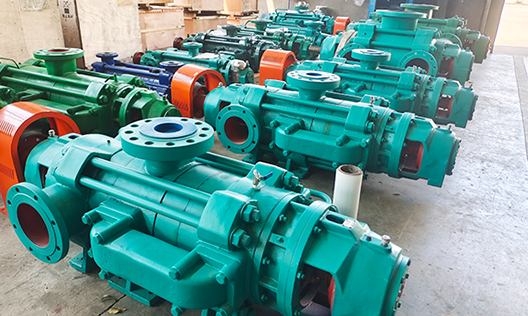
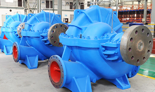
Puede fabricar 26 series de productos, incluyendo bombas de circulación para grandes centrales eléctricas, bombas de condensación para grandes centrales eléctricas, bombas petroquímicas, bombas multietapa, bombas de aguas residuales y lodo, bombas multietapa autoequilibradas, bombas de doble succión y única etapa tipo split, y bombas centrífugas de succión simple y única etapa.
-
Cases
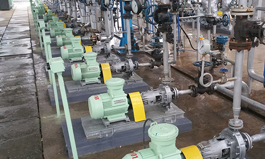
La elección de más de cientos de miles de clientes, cubriendo industrias como minería de carbón, metalurgia, química, energía, recursos hídricos, alimentos, municipalidades y protección ambiental, y exportando a Asia Sudeste, África, América y otros lugares.
-
Service
La empresa fue la primera en la industria en obtener las certificaciones internacionales del sistema de calidad ISO 9001:2008, del sistema de gestión ambiental ISO 14001 y del sistema de gestión de seguridad y salud ocupacional GB/T 28001, además de la certificación API 610 de la Asociación Estadounidense del Petróleo.
-
About us
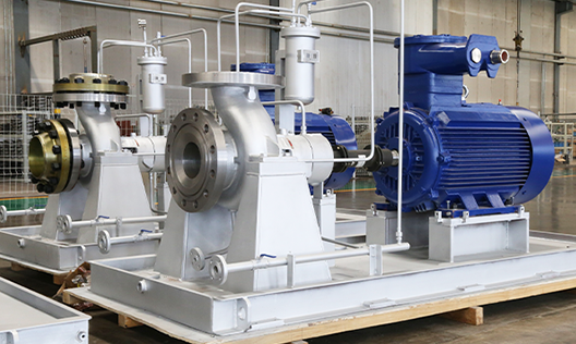
La empresa, fundada en 1989, es una empresa nacional de alta tecnología integral que integra diseño, investigación y desarrollo, fabricación y servicios; actualmente es una empresa clave en la industria china de bombas centrífugas y una de las grandes fábricas especializadas.
-

Blogs
Con productos innovadores, calidad excepcional y servicios integrales, buscamos la verdad y la pragmática, avanzamos con iniciativa, y nos esforzamos por lograr el objetivo de ser "la marca líder en el campo de aplicación de bombas centrífugas en el país"! Raigada en Hunan, orientada a todo el país y hacia el mundo!
Causes of Cavitation in Centrifugal Pumps and Professional Prevention Strategies
Publication Date:
2025-11-17
Author:
Source:


As a core fluid-handling device in industries, agriculture, municipal water supply, and other sectors, the stable operation of centrifugal pumps directly impacts production efficiency and equipment lifespan. Cavitation, one of the most common failures in centrifugal pump operation, occurs when local pressure within the pump drops to the saturation vapor pressure corresponding to the liquid's temperature, causing the liquid to vaporize and form bubbles. These bubbles are then carried by the flow into high-pressure regions, where they collapse abruptly. This violent implosion generates intense shock waves, leading to impeller erosion, pump body vibration, and a sharp decline in efficiency—and in severe cases, even resulting in complete equipment failure. In this article, the centrifugal pump manufacturer Changsha Zhonglian Pump Industry The technical engineer will explain the causes of cavitation in centrifugal pumps and provide practical solutions for prevention and control.

I. The Core Cause of Cavitation in Centrifugal Pumps
The occurrence of cavitation in centrifugal pumps fundamentally stems from a mismatch between the pump's inherent anti-cavitation capability and the operating conditions of the system, with its core constrained by two major factors:
(1) Pump Body's Own Design and Manufacturing Factors
The inherent performance of a centrifugal pump directly determines its cavitation resistance. If the curvature of the impeller inlet passage is inappropriate, the blade inlet thickness is excessive, or the surface finish is inadequate, it can lead to increased pressure loss at the inlet, making it easier for fluid conditions to reach vaporization. Meanwhile, the pump's required net positive suction head (NPSH) NPSHr , meaning the minimum energy required for the pump to avoid cavitation)—if the parameter design is set too high or if anti-cavitation materials are not used during manufacturing, this will also weaken its inherent resistance to erosion. Notably, the required net positive suction head (NPSH) is directly proportional to the square of the rotational speed; therefore, designing for high speeds without incorporating corresponding erosion-resistant structures can significantly increase the risk of cavitation.
(II) System Configuration and Operational Condition Factors
These are the primary triggers of cavitation during operation, specifically including:
1. Improper installation elevation: Installing at too high an elevation can reduce the effective net positive suction head at the pump inlet. NPSHa , which refers to the actual remaining energy imported), when NPSHa < NPSHr At that moment, cavitation will inevitably occur.
2. Defects in the inflow pipeline and intake basin: Excessively long pipelines, undersized pipe diameters, and an overabundance of fittings can increase head loss. Additionally, irregular shapes in the intake basin, accumulation of debris, or insufficient submergence depth at the bellmouth can lead to vortex formation, drawing in air and disrupting flow stability.
3. Operating conditions deviating from design values: Centrifugal pumps under high-flow conditions, NPSHr It increases proportionally to the square of the flow rate, and if operated under overload for an extended period, it can easily exceed the cavitation resistance limit.
4. Media characteristics impact: Highly sediment-laden media can accelerate wear on flow components, compromise surface smoothness, and simultaneously increase fluid resistance, indirectly triggering cavitation.
II. Scientific Solutions for Centrifugal Pump Cavitation
Cavitation prevention and control require a balanced approach that integrates "inherent optimization" with "post-operative management," employing multi-dimensional strategies that combine pump design, equipment configuration, and operational management.
(1) Optimize Device Design and Installation
1. Precise calculation of installation elevation: Based on the pump specifications provided NPSHr Parameters, combined with local atmospheric pressure, medium temperature (which affects vaporization pressure), pipeline losses, and more, are calculated using the following formula: ` Installation elevation ≤ NPSHa - NPSHr Calculate and reserve 0.5–1 Safety margin for temperature. If conveying high-temperature liquids (such as 80 Above ℃), the calculated values need to be adjusted, and if necessary, the pump should be installed below the liquid level to create backflow.
2. Standardize the design and maintenance of intake basins: The intake basin should feature a streamlined structure to ensure smooth water flow, and sediment and debris must be regularly removed. Additionally, the submergence depth of the intake nozzle must be no less than 1.5 Increase the pipe diameter to prevent the formation of an intake vortex.
3. Optimize the inlet pipeline configuration: Follow the principles of "short, straight, and wide," appropriately increase the pipe diameter to reduce flow velocity, and minimize the use of gate valves as much as possible. 90 °Bends, reducers, and other redundant accessories. The length of the horizontal straight section upstream of the horizontal centrifugal pump inlet must be no less than 4-5 Double the pipe diameter to ensure uniform pressure and flow velocity distribution.
(II) Standardize Operational Management
1. Adhere to the designed operating conditions: Avoid prolonged operation of the pump under high-flow, low-head conditions by employing methods such as variable-frequency speed control and valve adjustments. For centrifugal pumps, it’s appropriate to slightly reduce the flow rate, shifting the operating point to the left; however, for axial-flow pumps, the operating point must be adjusted to ensure optimal performance. NPSHr Minimum value area.
2. Properly regulate the operating speed: Utilizing variable-frequency technology to reduce the speed can enable NPSHr It decreases proportionally to the square of the rotational speed, effectively mitigating cavitation. Under the condition of meeting the head requirement, prioritizing a low-speed operation scheme is more economical and safer.
3. Moderate air intake buffering: Introducing a small amount of air at the pump inlet side can help reduce the impact force of bubble collapse and lower local vacuum levels. However, the air intake must be strictly controlled—typically not exceeding a fraction of the flow rate. 1% ), avoiding any impact on water absorption performance.
(3) Enhance the Corrosion Resistance of the Pump Body
1. Enhancing Manufacturing and Repair Quality: Flow components such as impellers and pump casings must ensure smooth surface finishes. Ra ≤ 1.6 μ m ), reducing hydraulic losses; for components already showing erosion, repair can be achieved by applying coatings such as tungsten carbide or epoxy resin, thereby extending service life and restoring efficiency.
2. Optimize the pump body structure design: Installing an inducer wheel upstream of the impeller can increase the cavitation specific speed to 3000 Above, this significantly enhances corrosion resistance; alternatively, a modular conical seal ring can be used to introduce high-pressure fluid from the outlet pipe into the inlet for boosting pressure and reducing NPSHr Demand.
3. When selecting corrosion-resistant materials for products: In scenarios with higher sand content, it's recommended to directly use specialized equipment such as wear-resistant slurry pumps. For standard pumps, impellers can be manufactured using high-strength, corrosion-resistant materials like stainless steel or duplex steel, helping to minimize cavitation damage.
(IV) Specialized Treatment for Unusual Operating Conditions
For water sources with high sediment content, it is necessary to install pre-treatment facilities such as sedimentation basins and filters at the inlet to keep the sand content within the pump's allowable range. In scenarios requiring high head pressure, a "pre-mounted booster pump" can be used. + "Main pump" combination, actively increasing the inlet pressure to meet NPSHa Requirements.
Cavitation in centrifugal pumps is not an uncontrollable failure—rather, the key lies in accurately identifying its root causes and implementing systematic measures such as "design optimization, installation standards, rational operation, and timely repairs." From the selection stage onward, attention should be focused on the pump body. NPSHr Parameters, coupled with strict control of operating conditions and maintenance quality, directly influence the cavitation resistance in every step. By appropriately applying the methods mentioned above, not only can cavitation damage be avoided, but pump life can also be extended and operational efficiency enhanced—empowering the stability of your production system.
Recommended Information


Related Products
Perhaps you also want to know?
Zoomlian Pump Industry
Address:No. 210, Environmental Protection Middle Road, Yuhua Economic Development Zone, Changsha City, Hunan Province China
All rights reserved © Changsha Zoomlian Pump Co., Ltd.
This website supports IPv4 IPv6 bidirectional access
Website construction:Zhongqi Power Changsha