

-
Products
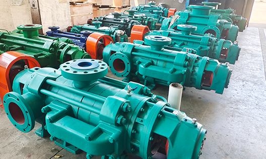
Puede fabricar 26 series de productos, incluyendo bombas de circulación para grandes centrales eléctricas, bombas de condensación para grandes centrales eléctricas, bombas petroquímicas, bombas multietapa, bombas de aguas residuales y lodo, bombas multietapa autoequilibradas, bombas de doble succión y única etapa tipo split, y bombas centrífugas de succión simple y única etapa.
-
Cases
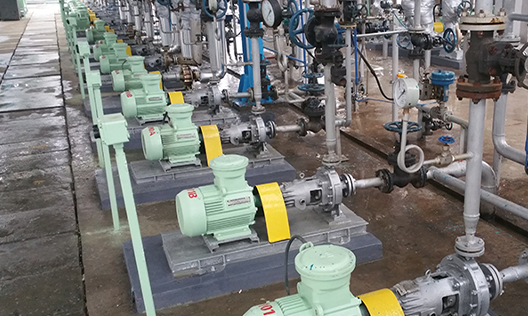
La elección de más de cientos de miles de clientes, cubriendo industrias como minería de carbón, metalurgia, química, energía, recursos hídricos, alimentos, municipalidades y protección ambiental, y exportando a Asia Sudeste, África, América y otros lugares.
-
Service
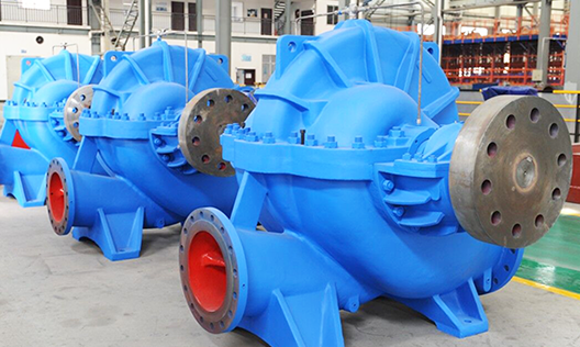
La empresa fue la primera en la industria en obtener las certificaciones internacionales del sistema de calidad ISO 9001:2008, del sistema de gestión ambiental ISO 14001 y del sistema de gestión de seguridad y salud ocupacional GB/T 28001, además de la certificación API 610 de la Asociación Estadounidense del Petróleo.
-
About us
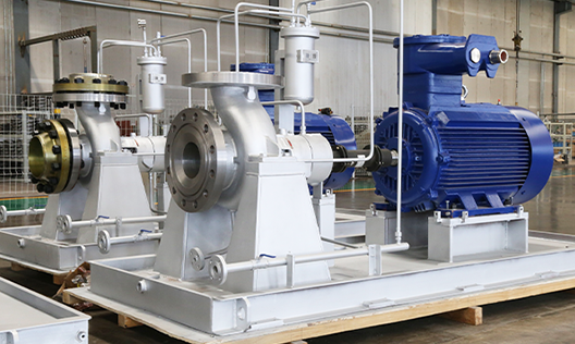
La empresa, fundada en 1989, es una empresa nacional de alta tecnología integral que integra diseño, investigación y desarrollo, fabricación y servicios; actualmente es una empresa clave en la industria china de bombas centrífugas y una de las grandes fábricas especializadas.
-

Blogs
Con productos innovadores, calidad excepcional y servicios integrales, buscamos la verdad y la pragmática, avanzamos con iniciativa, y nos esforzamos por lograr el objetivo de ser "la marca líder en el campo de aplicación de bombas centrífugas en el país"! Raigada en Hunan, orientada a todo el país y hacia el mundo!
Product Center
Feed pump for medium pressure boiler DG (BB4)
Flow: 35-580m³/h
Lifting height: 270-2150m
Power: 4-4500kw
Efficiency: 42%-84%
Weight of the pump: 78-1963kg
Cavitation margin: 2.0-7.0m
Price: 0.81-16.8 thousand
Suitable for transporting clean water with a medium temperature of -20℃ to 160℃ (average pressure not exceeding 105℃), or non-corrosive liquids with physical-chemical properties similar to water, the pump's inlet pressure must not exceed 0.59M (6kgf/cm2). Widely used in power plants, metallurgy, heating, and other sectors for supplying water to boilers, also suitable for unit systems and main pipeline systems of various capacities in power plants.
Product description
The medium pressure boiler feed pump DG is suitable for transporting clean water with a medium temperature of -20℃ to 160℃ (the medium pressure does not exceed 105℃), or non-corrosive liquids with physical-chemical properties similar to water. The pump's inlet pressure should not exceed 0.59M (6kgf/cm2). It is widely used in power plants, metallurgy, heating, and other sectors for boiler feeding, and is also suitable for boiler feed systems of units and main pipeline systems in power plants of various capacities. The maximum height can reach 1800 meters. The medium pressure boiler feed pump DG, as a high-pressure boiler feed pump or another high-pressure feed pump, is an efficient and energy-saving product specially designed for the upgrading and modernization of new series of industrial steam boilers. It is not only suitable for medium and low pressure boiler feeding but also for transporting water to great heights in factories and cities.

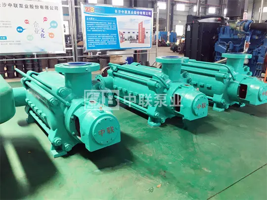
↑Medium pressure boiler feed pump series DG280-65×6↑
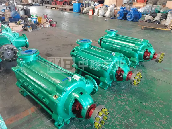
The high pressure boiler feed pump DG is a multi-stage centrifugal pump with single suction, belonging to the series of multi-stage high pressure pumps. The pump casing can be axially disassembled along the axis line. The model DG85-80×8 pump has its suction inlet oriented vertically upwards and the outlet also vertically upwards, perpendicular to the axis. From the drive side, the pump rotates clockwise; it can also be manufactured with counterclockwise rotation according to user needs, which must be specified when ordering.
Explanation of the medium pressure boiler feed pump model DG
Example of model: DG45-80×6
DG — medium pressure boiler feed pump with single suction and multiple stages
45 — design flow rate of the pump
80 — lift height per stage of the pump
6 — number of stages of the pump
Structural characteristics of the medium pressure boiler feed pump DG

Bearing balance: The rotor of the high pressure boiler pump DG is supported by ball bearings at both ends of the pump shaft. Lubrication with fine oil and cooling with circulating water; the axial force of the rotor is automatically balanced by a balance disk. The balance water returns to the suction section of the pump through the balance return pipe. The rotor of the medium pressure pump DG is supported by sliding bearings at both ends of the pump shaft. Lubrication with fine oil and cooling with circulating water; the axial force of the rotor is balanced by a balance disk. Between the balance chamber and the front section, a water return pipe is installed. The rotor of the high pressure boiler pump DG is supported by sliding bearings at both ends of the pump shaft. The bearings have forced lubrication, the pump is equipped with an oil system, and the axial force of the rotor is balanced by a balance disk. In addition, it has a thrust bearing to support the residual axial force generated by changes in working conditions. Between the balance chamber and the suction pipe, a water return pipe is installed.
Transmission: The medium and medium-high pressure multi-stage pumps are driven by a motor through an elastic coupling. From the transmission direction, the pump rotates clockwise. The high pressure pumps are also driven by a motor through an elastic coupling, and according to user needs, they can be equipped with toothed couplings, diaphragm couplings, or hydraulic couplings. The motor can be a small steam turbine or an electric motor. From the transmission direction, the pump rotates clockwise. The casing and cover of the boiler feed pump form the working chamber of the impeller. On the water inlet and outlet flanges, there are threads to install vacuum and pressure gauges. At the bottom of the casing, there are threads to drain the residual water.
The impeller is of single suction and closed type, equipped with a balance disk to balance most of the axial force, and also has a thrust bearing to support the small residual part of the axial force. The arrangement of the bearings keeps the shaft in a stable state of tension bar. Before assembly, the impeller must undergo strict static balance verification to ensure stable operation.
The pump shaft is supported by two Babbitt alloy sliding bearings, installed in the bearing housing of the pump support and lubricated with fine oil.
In the pump casing, there is a sealing ring that can improve the volumetric efficiency of the pump and, on the other hand, prevent the backflow of high-pressure water into the suction chamber, disturbing the inlet flow field, thus ensuring the suction performance of the pump.
The shaft seal is generally a soft packing seal. During the operation of the pump, a small amount of medium can be led into the packing box, and external cooling and lubrication water can also be connected to fulfill water sealing and lubrication functions. According to user needs, the packing seal can be replaced with a mechanical seal.
Main materials of the parts of the medium pressure boiler feed pump DG
| ● Inlet and outlet section: ZG230-450 | ● Middle section: ZG230-450 | ● Guide vanes: QT450 |
| ● Impeller: QT450 | ● Main shaft: 40Cr | ● Sealing ring: QT450 |
| ● Shaft sleeve: HT250 | ● Balance disk: ZG2Cr13 | ● Balance ring: tin bronze |
Kind notice: The user can communicate with the technical staff of Zhonglian Pump Industry to make a reasonable configuration according to the site conditions and needs.
Steps for installing the medium pressure boiler feed pump DG
1. Preparation
Before assembly, all pump parts, especially the finishing surfaces that fit together, must be thoroughly cleaned.
Count all parts and classify and number them according to the assembly order.
2. Assembly of the pump parts
Pay attention to correctly install the sealing ring of the middle section to prevent it from falling off.
Pay attention to correctly align the anti-rotation pin of the guide vanes.
Tighten the nuts of the through bolt of the pump body symmetrically to maintain proper tension; if it is too loose, it may cause leaks at the joint surface of the middle section; if it is too tight, it may deform the stator parts. The tightening torque during assembly is approximately 5550 Nm. Tighten the through bolt symmetrically.
After basically tightening the through bolt, use an indicator to check that the non-parallelism between the front and rear sections is ≤0.1mm. Measure the total eccentricity of the rotor, which must meet the requirements of the drawing.
Install the front cover bearing and the low-pressure end cover and the lower support, and raise the shaft to the central position.
Use special tools and a micrometer to check the oscillation of the balance sleeve end, it must meet the requirements of the general assembly drawing.
Assemble the rotor parts and tighten the locking nut. The measurement of misalignment after installing the balance disc must meet the requirements of the general assembly drawing.
Install the front and rear covers at both ends, the bearing body, and the space on the top and sides of the bushings, it must meet the specified values in the bushing quality requirements.
Adjust the center of the bushings on both sides, and after adjusting, tighten the adjusting nut.
3. Assembly of the thrust bearing
The assembly of the thrust bearing parts must scrape and sand the black metal sheets according to the requirements of the bearing parts; during assembly, the thrust sheets must rotate flexibly. 1.9.2 After installing the thrust bearing, the axial space between the balance disc and the balance sleeve must be 0.04 to 0.08 mm according to the requirements of the general assembly drawing, the adjustment of the space is done with an adjustment ring.
After adjusting the space, install the thrust bearing and the thrust disc, and tighten the locking nut.
The pump body and the cover form the working chamber of the impeller; on the water inlet and outlet flanges, there are threaded holes to install vacuum and pressure gauges; at the bottom of the pump body, there are threaded holes to drain the wastewater.
The impeller is of single suction and closed type, equipped with a balance disk to balance most of the axial force, and also has a thrust bearing to support the small residual part of the axial force. The arrangement of the bearings keeps the shaft in a stable state of tension bar. Before assembly, the impeller must undergo strict static balance verification to ensure stable operation.
The pump shaft is supported by two Babbitt alloy sliding bearings, installed in the bearing housing of the pump support and lubricated with fine oil.
In the pump casing, there is a sealing ring that can improve the volumetric efficiency of the pump and, on the other hand, prevent the backflow of high-pressure water into the suction chamber, disturbing the inlet flow field, thus ensuring the suction performance of the pump.
The shaft seal is generally a soft packing seal. During the operation of the pump, a small amount of medium can be led into the packing box, and external cooling and lubrication water can also be connected to fulfill water sealing and lubrication functions. According to user needs, the packing seal can be replaced with a mechanical seal.
The space between the thrust bearing seat and the thrust disc is adjusted with wedges to ensure that the thrust bearing space requirements are met according to the general assembly drawing.
Instructions for use of the high-pressure boiler feed pump type DG
1. Start-up
Before starting the pump, rotate the pump rotor to check if the rotor rotates flexibly;
Check that the motor direction matches the pump rotation direction;
Open the pump suction valve, close the gate valve and the gauge plug in the outlet pipe to fill the pump with liquid, or use a vacuum system to remove air from the suction pipe and the pump;
Check the tightening of the connection bolts between the pump and the motor and the safety around the pump to ensure it is ready to start;
Start the motor, when the pump is running normally, slowly open the gauge plug and gradually open the outlet gate valve until the gauge needle indicates the required pressure (control the lift height given by the pump according to the reading of the outlet gauge).
2. Operation
This pump balances axial force through an internal balancing mechanism; the balancing liquid flows from the balancing device to the inlet section through a balancing pipe, or a short tube is designed outside the balancing chamber for the balancing liquid to flow outside the pump. To ensure the normal operation of the pump, the balancing pipe must not be blocked under any circumstances;
During start-up and operation, carefully observe the instrument readings, bearing heating, leakage, and packing heating, as well as the vibration and sound of the pump; if any anomalies are detected, they must be addressed promptly;
The increase in bearing temperature reflects the quality of the pump assembly; the bearing temperature must not exceed 35℃ above ambient temperature, and the maximum bearing temperature must not exceed 75℃;
The pump rotor exhibits some axial movement during operation, the axial movement must be within the allowed range, ensuring the space between the faces of the motor and pump couplings;
During operation, periodically inspect the wear of parts such as the impeller, sealing ring, guide sleeve, shaft sleeve, and balance disc; if the wear is excessive, they must be replaced in time.
3. Stopping
Before stopping the pump, first close the gauge plug, slowly close the outlet gate valve, after completely closing the outlet valve, stop the motor, and once the pump is stopped, close the suction valve; drain the water inside the pump; if it is to be left unused for a long time, disassemble, clean, lubricate, and store the pump.
Assembly and disassembly of the high-pressure boiler feed pump type DG
1. Precautions when disassembling the pump
Stop the pump following the stopping order;
Drain the liquid inside the pump housing (including cooling water); if the bearings are lubricated with light oil, drain the lubricating oil;
Disassemble auxiliary pipes that hinder disassembly, such as balancing pipes, water seal pipes, and cables;
Disassembly must strictly protect the manufacturing precision of the parts to avoid damage; when disassembling the through shaft, the middle sections must be supported with blocks to prevent the housings from loosening and sinking, which could bend the shaft.
2. Disassembly order of the pump
Unscrew the bolts of the bearing cover on the discharge side and the connection bolts between the outlet section, the rear cover, and the bearing body, remove the bearing cover, the bearing body, and other bearing parts;
Unscrew the round nut of the shaft and sequentially remove the inner ring of the bearing, the bearing cover, and the retaining ring, then remove the packing body (including the packing cover, the packing ring, and the packing);
Sequentially remove the O-ring seal, the shaft sleeve, the balance disc, and the shaft key, then disassemble the outlet section, the last guide, and the balance ring sleeve;
After removing the last stage impeller and the key, disassemble the middle section and the guide; continue disassembling the impellers of each stage, the middle section, and the guide until the first stage impeller is disassembled;
After disassembling the pump coupling, unscrew the connection nut between the inlet section and the bearing body and the bolts of the bearing cover, then disassemble the bearing parts on the inlet side;
Extract the shaft from the inlet section, unscrew the fixed nut of the shaft and sequentially remove the inner ring of the bearing, the O-ring seal, and the shaft sleeve;
For pumps with sliding bearings, the disassembly order is basically the same, except that the disassembly of the bearing parts is slightly different.
3. Assembly of the pump
The assembly order of the pump is generally done in the reverse order of disassembly. The quality of the assembly directly affects whether the pump can operate normally, as well as the lifespan and performance parameters of the pump. During assembly, the following points must be considered:
The machining accuracy and surface roughness of the parts must be protected, and damages such as dents or scratches are not allowed; the molybdenum disulfide used for sealing must be clean, and the screws and fastening bolts must be evenly tightened.
The alignment between the outlet duct of the impeller and the inlet duct of the guide is guaranteed according to the axial dimensions of each part; the quality of this alignment directly affects the performance of the pump, so the dimensions of the pump should not be adjusted arbitrarily.
After assembling the pump, before installing the packing, manually rotate the pump rotor to check if it rotates smoothly and if the axial play meets the specified requirements.
After passing inspection, press the packing and pay attention to the relative position of the packing ring in the packing chamber.
Product parameters
Performance range of the secondary pressure boiler feed pump type DG
| ● Flow range: | ● Lift height range: |
| Q=100~580m3/h (high pressure DG) | H=740~2150m (high pressure) |
| Q=36~180m3/h (secondary pressure) | H=409~1056m (secondary pressure) |
| Q=36~180m3/h (medium pressure) | H=270~672m (medium pressure) |
| ● Transport temperature: -20-205℃ (indicate if above 150℃) | ● Suction pressure: 0-7.5MPa (indicate if above 0.5 MPa) |
Performance parameter table of the secondary pressure boiler feed pump type DG
| Model Series |
Flow range (m³/h) |
Lift height range (m) |
Efficiency range (%) |
Associated power range (kw) |
| DG6-25 | 3.75~7.5 | 70.35~320.3 | 36~49.5 | 5.5~18.5 |
| DG6-50 | 3.75~7.5 | 144~624 | 28~30 | 15~55 |
| DG6-80 | 3.75~7.5 | 225~982 | 32~36 | 15~75 |
| DG12-25 | 7.5~15 | 68.3~325.3 | 43.3~52.1 | 7.5~30 |
| DG12-50 | 7.5~15 | 142.7~635 | 30.6~44.6 | 18.5~75 |
| DG12-80 | 7.5~15 | 225~982 | 37~40 | 30~132 |
| DG25-30 | 15~30 | 77.7~418.8 | 55.2~56.9 | 15~55 |
| DG25-50 | 15~30 | 144~618 | 44~54 | 22~110 |
| DG25-80 | 15~30 | 228~1013 | 47~56 | 37~160 |
| DG46-30 | 30~55 | 76.2~429 | 60~66.8 | 22~90 |
| DG46-50 | 30~55 | 138.3~658.8 | 53.6~64.5 | 37~160 |
| DG46-80 | 30~55 | 228~1056 | 59~65 | 55~250 |
| 80D12 | 21.6~39.6 | 19~129.6 | 69~75 | 4~18.5 |
| DG65-80 | 50~75 | 228~1056 | 60~67 | 75~315 |
| 100D16 | 37.6~72 | 20.4~178.2 | 66~73 | 7.5~37 |
| DG85-45 | 55~100 | 121.8~612 | 64.2~70.4 | 55~200 |
| DG85-67 | 55~100 | 186.9~888 | 56.1~68.4 | 90~315 |
| DG85-80 | 55~100 | 228~1056 | 59~71 | 110~450 |
| DG85-150 | 55~100 | 429~1872 | 53~60 | 220~900 |
| DG100-25 | 72~119 | 46~270 | 63.4~69 | 30~132 |
| DG100-55 | 85~120 | 147~708 | 64.4~68 | 90~315 |
| DG120-50 | 96~140 | 126.9~654 | 72~78 | 90~280 |
| DG120-67 | 96~140 | 183~840 | 62~71 | 110~450 |
| DG120-80 | 96~140 | 216~1056 | 61.6~70.4 | 132~560 |
| DG120-100 | 96~140 | 261.6~1320 | 69.5~73 | 220~900 |
| 125D25 | 72~119 | 35~230.4 | 70.5~77.5 | 22~90 |
| DG150-50 | 120~180 | 127.5~660 | 72~75 | 110~400 |
| DG150-80 | 120~180 | 228~1056 | 65~75 | 185~710 |
| DG150-100 | 120~180 | 261.6~1320 | 69.5~73 | 220~900 |
| DG150-130 | 120~180 | 354~1644 | 62.5~64 | 315~1250 |
| DG155-30 (150D30) |
100~185 | 81.6~400.8 | 65.5~73.2 | 75~250 |
| DG155-67 | 100~185 | 179.4~895.2 | 63~74 | 132~560 |
| DG200-50 | 132~240 | 135~696 | 78~81 | 132~500 |
| DG200-80 | 132~240 | 216~1044 | 70.9~75 | 220~900 |
| DG200-100 | 132~240 | 252~1356 | 70~76 | 250~1000 |
| DG280-43 (200D43) |
185~335 | 116.1~564 | 70.5~76.7 | 160~630 |
| DG280-65 (200D65) |
185~335 | 184.5~816 | 63.3~74 | 250~1000 |
| DG280-95 | 185~335 | 273~1200 | 68~72.5 | 400~1600 |
| DG280-100 | 185~335 | 279~1248 | 58.6~72.6 | 400~1600 |
| DG300-65 | 240~350 | 180~828 | 69.2~69.5 | 315~1120 |
| DG360-40 | 300~440 | 106.5~504 | 77~80 | 185~710 |
| DG360-60 | 300~440 | 157.5~768 | 71~74.5 | 355~1250 |
| DG360-95 | 300~440 | 267~1224 | 70~73 | 500~2000 |
| DG420-95 | 350~500 | 263~1192 | 67.9~71 | 560~2240 |
| DG450-40 | 330~500 | 112.5~528 | 73.9~76.9 | 220~1000 |
| DG450-60 (250D60) |
335~500 | 162.9~765.6 | 74.1~78.9 | 355~1400 |
| DG450-95 | 335~500 | 267~1200 | 72~75 | 560~2240 |
| DG500-57 | 375~555 | 109.6~717.6 | 69.7~82.6 | 220~1400 |
| DG550-40 | 400~600 | 76~528 | 75.1~78.4 | 185~1120 |
| DG550-50 | 400~600 | 95~660 | 75.1~77.8 | 220~1400 |
| DG550-95 | 400~600 | 182~1230 | 70.9~72.4 | 450~2800 |
| DG580-60 | 450~640 | 113~780 | 75.5~76.8 | 280~1800 |
| DG580-100 | 450~640 | 190~1284 | 70~74 | 500~2800 |
| DG600-60 | 450~710 | 104~780 | 79~82 | 280~1800 |
| DG600-85 | 450~710 | 162~1092 | 72.4~73.6 | 450~2800 |
| DG650-80 | 540~715 | 154~1005 | 73.5~75.5 | 450~2800 |
| DG650-100 | 540~715 | 193~1256 | 79.2~83 | 500~2800 |
| DG720-60 | 550~850 | 106.8~738.1 | 79.2~82.4 | 355~2240 |
| DG720-80 | 550~850 | 149~931.8 | 72.9~76 | 630~2800 |
| DG720-100 | 550~850 | 186~1059 | 76.5~84 | 560~2800 |
| DG800-80 | 620~900 | 150~951.5 | 73~81 | 500~2800 |
Kind advice: click on the specific model series above to see more detailed parameters and corresponding performance curve graphs.

Why Choose Us?
Changsha Zhonglian Pump Industry Co., Ltd. was established in 1989, following the reform of the Changsha Water Pump Factory. It is a national high-tech comprehensive enterprise integrating design, research and development, manufacturing, and service. The company was listed on the Hunan Provincial Stock Exchange on December 31, 2019, with the abbreviated name "Zhonglian Pump Industry" and stock code: 600275HN. It is currently a key enterprise in China's centrifugal pump industry and one of the leading domestic manufacturers of multi-stage pumps, headquartered in Changsha, Hunan, a historical and cultural city in China.

FAQ
Q
What products do you mainly produce?
A
Q
Can you help me choose a model?
A
Q
Why is the price quotation so slow?
A
Q
What information should I provide when I need a quote?
A
Q
Do you have centrifugal pumps in stock?
A
Q
What is your usual delivery time?
A
Models in stock can be shipped by the next day at the latest. Others are custom-made, and depending on the product size and specific project conditions, the delivery time is generally between 7-90 days. Please consult our sales manager for details: 0731-88632200 。
Online Inquiry
Attention: Please leave your contact information, our professional staff will contact you as soon as possible!
Perhaps you also want to know?
Zoomlian Pump Industry
Address:No. 210, Environmental Protection Middle Road, Yuhua Economic Development Zone, Changsha City, Hunan Province China
All rights reserved © Changsha Zoomlian Pump Co., Ltd.
This website supports IPv4 IPv6 bidirectional access
Website construction:Zhongqi Power Changsha