

-
Products
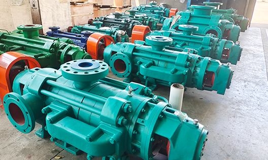
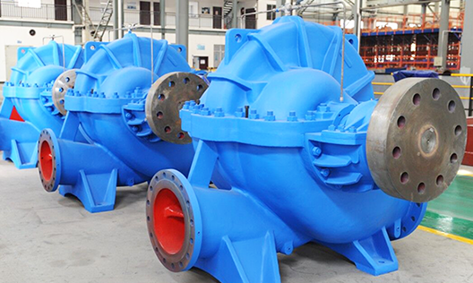
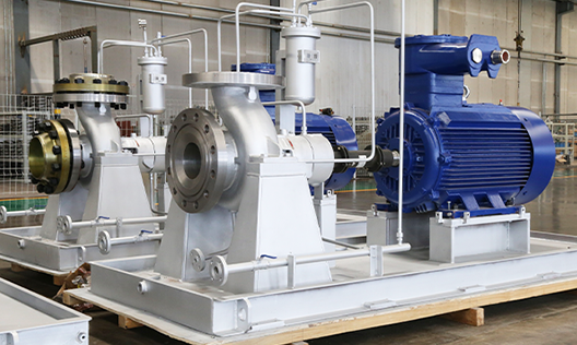
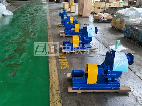
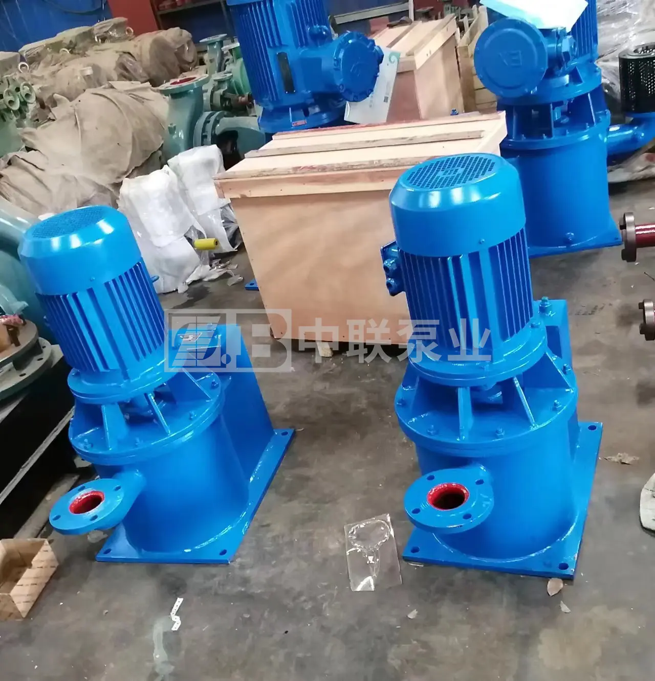
Puede fabricar 26 series de productos, incluyendo bombas de circulación para grandes centrales eléctricas, bombas de condensación para grandes centrales eléctricas, bombas petroquímicas, bombas multietapa, bombas de aguas residuales y lodo, bombas multietapa autoequilibradas, bombas de doble succión y única etapa tipo split, y bombas centrífugas de succión simple y única etapa.
-
Cases
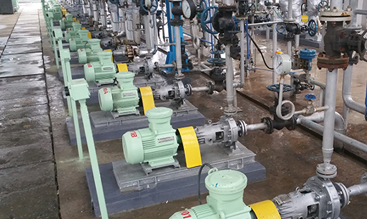
La elección de más de cientos de miles de clientes, cubriendo industrias como minería de carbón, metalurgia, química, energía, recursos hídricos, alimentos, municipalidades y protección ambiental, y exportando a Asia Sudeste, África, América y otros lugares.
-
Service
La empresa fue la primera en la industria en obtener las certificaciones internacionales del sistema de calidad ISO 9001:2008, del sistema de gestión ambiental ISO 14001 y del sistema de gestión de seguridad y salud ocupacional GB/T 28001, además de la certificación API 610 de la Asociación Estadounidense del Petróleo.
-
About us
La empresa, fundada en 1989, es una empresa nacional de alta tecnología integral que integra diseño, investigación y desarrollo, fabricación y servicios; actualmente es una empresa clave en la industria china de bombas centrífugas y una de las grandes fábricas especializadas.
-
Blogs
Con productos innovadores, calidad excepcional y servicios integrales, buscamos la verdad y la pragmática, avanzamos con iniciativa, y nos esforzamos por lograr el objetivo de ser "la marca líder en el campo de aplicación de bombas centrífugas en el país"! Raigada en Hunan, orientada a todo el país y hacia el mundo!
Product Center
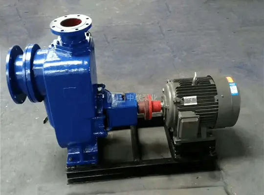
Self-priming stainless steel pump type JMZ
Flow: 3-100m³/h
Lifting height: 22-40m
Power: 1.1-15kw
Suction height: 5-6m
Rotation speed: 2900r/min
Price: 31500-152000
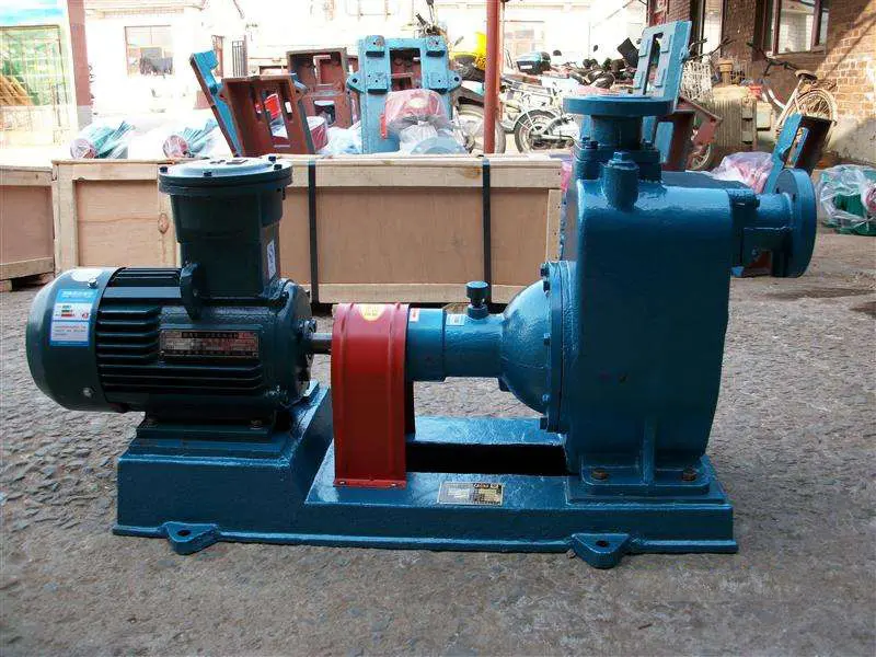
The JMZ type stainless steel self-priming pump is a stainless steel self-priming pump recently developed by our company, also known as a wine pump. This self-priming pump uses our new set of mechanical seals, safe and explosion-proof, which guarantees no leaks for years. It is suitable for pumping and transporting various corrosive liquids such as alcohol, chemical agents, gasoline, beverages, dairy products, solvents, syrups, etc., within a temperature range of -35 to +120 °C.
Product Description

Product parameters


Why Choose Us?
Changsha Zhonglian Pump Industry Co., Ltd. was established in 1989, following the reform of the Changsha Water Pump Factory. It is a national high-tech comprehensive enterprise integrating design, research and development, manufacturing, and service. The company was listed on the Hunan Provincial Stock Exchange on December 31, 2019, with the abbreviated name "Zhonglian Pump Industry" and stock code: 600275HN. It is currently a key enterprise in China's centrifugal pump industry and one of the leading domestic manufacturers of multi-stage pumps, headquartered in Changsha, Hunan, a historical and cultural city in China.

FAQ
Q
What products do you mainly produce?
A
Q
Can you help me choose a model?
A
Q
Why is the price quotation so slow?
A
Q
What information should I provide when I need a quote?
A
Q
Do you have centrifugal pumps in stock?
A
Q
What is your usual delivery time?
A
Models in stock can be shipped by the next day at the latest. Others are custom-made, and depending on the product size and specific project conditions, the delivery time is generally between 7-90 days. Please consult our sales manager for details: 0731-88632200 。
Online Inquiry
Attention: Please leave your contact information, our professional staff will contact you as soon as possible!
Perhaps you also want to know?
Zoomlian Pump Industry
Address:No. 210, Environmental Protection Middle Road, Yuhua Economic Development Zone, Changsha City, Hunan Province China
All rights reserved © Changsha Zoomlian Pump Co., Ltd.
This website supports IPv4 IPv6 bidirectional access
Website construction:Zhongqi Power Changsha