Operating principle of the SZ series water ring vacuum pump:

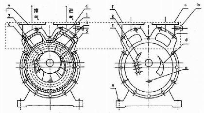
Figure 1 Figure 2
Structural diagram of the water ring vacuum pump and compressor
1. Impeller 2. Pump body 3. Water ring 4. Suction pipe 5. Suction port 6. Discharge port 7. Discharge pipe a. Base b. Vacuum regulating valve c. Suction pipe d. Suction port e. Rubber valve f. Discharge pipe g. Discharge port u. Water inlet port
The SZ water ring vacuum pump, as shown in Figure 1, has an impeller ① mounted eccentrically inside the pump body ②. When starting, a certain amount of water is injected into the pump.
Therefore, when the impeller rotates, the water, under the action of centrifugal force, forms a rotating water ring ③ on the wall of the pump body. The upper inner surface of the water ring is tangential to the hub and rotates in the direction of the arrow. During the first half of the rotation, the inner surface of the water ring gradually separates from the hub, so the SZ water ring vacuum pump forms a space between the impeller blades that gradually expands, thus drawing air through the suction port; during the second half of the rotation, the inner surface of the water ring gradually approaches the hub, and the volume of the space between the blades decreases, compressing and expelling the air between the blades.
In this way, each time the impeller makes one revolution, the volume of the space between the blades changes once, and the water between each blade acts as a piston that moves alternately, so the SZ water ring vacuum pump continuously sucks gas.
Because the water heats up during operation and part of the water is discharged along with the gas, the SZ water ring vacuum pump must continuously supply cold water during operation to cool and replenish the water consumed in the pump. A cold water temperature of 15 ℃ is recommended.
When the gas discharged by the SZ water ring vacuum pump is residual gas, a water tank is connected at the discharge end. After the residual gas and part of the water are discharged into the water tank, the gas is discharged through the water tank outlet pipe, while the water falls to the bottom of the water tank and returns to the pump through the return pipe. If the circulation time is long, the water will heat up, so a certain amount of cold water must be supplied from the water supply point of the water tank.
Because the water heats up during operation and part of the water is discharged along with the gas, the SZ water ring vacuum pump must continuously supply cold water during operation to cool and replenish the water consumed in the pump.
When the gas discharged by the SZ water ring vacuum pump is residual gas, a water tank is connected at the discharge end. After the residual water and part of the water are discharged into the water tank, the gas is discharged through the water tank outlet pipe, while the water falls to the bottom of the water tank and returns to the pump through the return pipe. If the water circulation time is long, the water will heat up, so a certain amount of cold water must be supplied from the water supply point of the water tank.
When the SZ water ring vacuum pump is used as a compressor, a water and gas separator must be connected at the discharge end. When the gas with water enters the separator, it separates automatically. The gas is sent to the required place through the separator outlet, while the hot water is automatically discharged through a switch. (Compressed gas tends to heat up, and the water becomes hot water after leaving the pump). The SZ water ring vacuum pump must also continuously supply cold water at the bottom of the separator to replenish the discharged hot water and for cooling.
Description of the structure of the SZ series water ring vacuum pump:

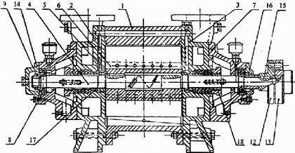
Figure 3
1. Pump body 2. Rear cover 3. Front cover 4. Pump shaft 5. Key 6. Impeller 7. Bearing support 8. Ball bearing 9. Lock nut 12. Pump coupling 13. Motor coupling 14. Bearing cover 15. Key 16. Positioning ring 17. Bushing 18. Stuffing box cover

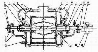
Figure 4
1. Pump body 2. Rear cover 3. Front cover 4. Pump shaft 5. Key 6. Impeller 7. Bearing support 8. Ball bearing 9. Lock nut 10. Water inlet pipe 11. Water sealing pipe 12. Pump coupling 13. Motor coupling 14. Bearing cover 15. Key 17. Bushing nut 18. Bushing 19. Stuffing box 20. Felt gasket 21. Stuffing box cover
The SZ vacuum pump consists of a pump body (1) and two side covers (2) (3) (Figures 3 and 4). The bottom of the side covers has pump feet (a) for support (Figure 2). At the top there are two pipes, a suction pipe (c) and a discharge pipe (f). These two pipes are connected to the pump chamber through the suction (d) and discharge (g) ports in the side covers. The suction pipe and discharge pipe in the SZ water ring vacuum pump body are connected to the suction and discharge ports in the side covers. The shaft (4) is mounted eccentrically in the pump body, and the impeller (6) is fixed to the shaft by a key (5). The space between the impeller and the side cover is adjusted by a gasket between the pump body and the side cover to adjust the total space. The bushing (17) drives the impeller to adjust the space at both ends of the impeller. This space determines the magnitude of gas leakage in the gas flow from the inlet to the outlet of the pump.
The stuffing box of the SZ vacuum pump is equipped inside the two side covers (2) (3). Behind the stuffing box, there is a water chamber. Water enters this chamber through the tube (11). Part of the water cools the stuffing box through the stuffing box, and the other part enters the pump body and, under the action of centrifugal force, flows along the end surface of the blades to fill the entire space between the impeller and the side cover.
The ball bearing (8) of the SZ water ring vacuum pump is fixed to the shaft by a circular nut (9).
The SZ vacuum pump has several rows of circular holes (e) with rubber (spherical) valves closed beneath the exhaust hole (g) on the side wall of the side cover (Figure 2). The function of these holes is that when the gas pressure between the impeller blades reaches the exhaust pressure, the gas is automatically discharged before the outlet, thus reducing the power consumed due to the high gas pressure.
As shown in the structure diagrams of SZ-1 and SZ-2 (Figure 3), the difference with the structure of SZ-3 and SZ-4 (Figure 4) is that the air inlet and outlet tubes are located in two side covers, one tube is connected to the air inlet and the other to the air outlet, and there is no rubber valve inside the pump.
The air inlet tube (10) of the SZ water ring vacuum pump is connected to the water and air separator to supply the circulation water necessary for the pump. To ensure a good seal between the two end surfaces of the pump chamber and the packing, the water sealing tube (11) must continuously supply clean cold water. At the coupling end, to prevent oil leakage from the bearing, a felt ring (20) is installed for sealing.
Technical parameters:
Note: 1. The vacuum of the SZ water ring vacuum pump, from 40% to 90%, or the pressure of 0.05 MPa, varies with the amount of water supplied and the clearance between the impeller and the side cover, especially when the flow rate is low; if the adjustment is not precise, a downward deviation is more likely to occur.
2. The values in the table of the SZ water ring vacuum pump are obtained under the following conditions:
① Water temperature 15℃
② Air temperature 20℃
③ Relative humidity of air 70%
④ Atmospheric pressure 0.1013 MPa
3. The performance deviation of the table does not exceed 5%.
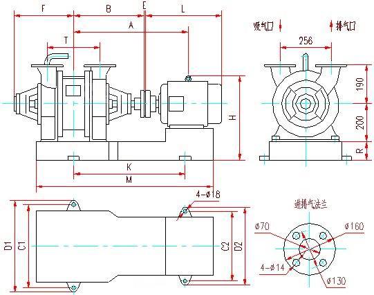
Installation dimensions:
Suggestion: For more performance parameters of the SZ series water ring vacuum pump, click →【Water Pump Selection】to consult.

Suggestion: For more performance parameters of the SZ series water ring vacuum pump, click →【Water Pump Selection】to consult.