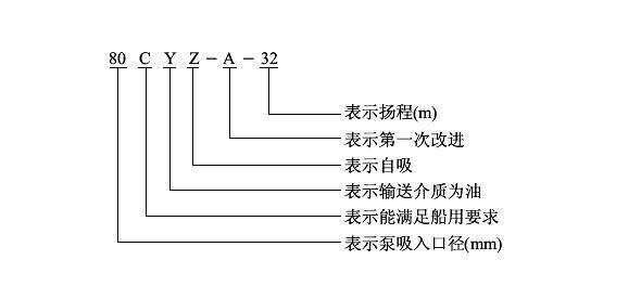
Meaning of the horizontal self-priming centrifugal pump model type CYZ:
Structural diagram and characteristics of the structural principle of the horizontal self-priming centrifugal pump type CYZ:
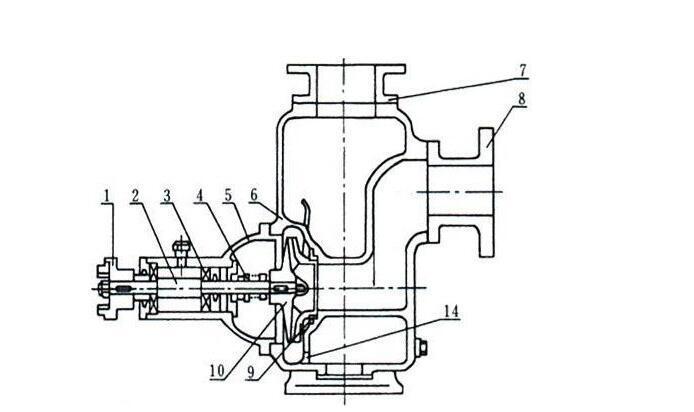
1 Coupling, 2 Pump shaft, 3 Bearing, 4 Mechanical seal, 5 Bearing housing, 6 Pump body, 7 Outlet support, 8 Inlet support, 9 Front seal ring, 10 Impeller, 11 Rear cover, 12 Water retaining ring, 13 Filling port, 14 Liquid return port
The CYZ type self-priming centrifugal pumps use a pump body structure with axial liquid return. The pump body consists of the suction chamber, liquid storage chamber, volute chamber, liquid return port, and gas-liquid separation chamber. After the pump starts normally, the impeller sucks the liquid stored in the suction chamber along with the air in the suction pipe, mixing them completely inside the impeller. Under the action of centrifugal force, the gas-carrying liquid flows to the outer edge of the volute chamber, forming a white foam band of a certain thickness and a liquid ring rotating at high speed at the outer edge of the impeller. The gas-liquid mixture passes through the diffuser tube to the gas-liquid separation chamber. At this moment, due to the sudden reduction in flow velocity, the lighter gas separates from the mixture and is expelled through the pump body outlet. The degassed liquid returns to the storage chamber and re-enters the impeller through the return port, mixing again with the gas sucked from the inlet pipe. Under the action of the high-speed rotating impeller, the liquid flows to the outer edge of the impeller... This process repeats continuously, gradually reducing the air in the suction pipe until it is completely eliminated, completing the self-priming process and allowing the pump to operate normally. Due to this unique degassing capability, this pump can transport liquids containing gas without the need to install a foot valve, and when used on oil tankers, it has a good tank cleaning function.
At the bottom of the bearing housing of some pumps, there is also a cooling chamber. When bearing heating causes the bearing housing temperature to exceed 70 °C, coolant can be injected through any cooling pipe connection for circulation cooling. The internal sealing mechanism that prevents liquid leakage from the high-pressure area to the low-pressure area consists of the front and rear seal rings; the front ring is installed in the pump body and the rear in the bearing housing. When the seal rings wear out after prolonged operation and affect the pump's efficiency and self-priming ability, they must be replaced.
Product features:
1. The CYZ type oil pump is a self-priming centrifugal pump that has the advantages of simple structure, convenient operation, stable performance, easy maintenance, high efficiency, long service life, and strong self-priming capacity. No foot valve is needed in the pipeline; before operation, it is only necessary to ensure a certain amount of liquid in the pump body. When used on oil tankers or water transport vessels, it can also function as a tank cleaning pump with good effect.
2. The CYZ type self-priming oil pump is made of high-quality materials and uses a durable hard carbide mechanical seal. There is no need to install a safety valve in the discharge pipe or a foot valve in the suction pipe, simplifying the piping system and improving working conditions.
Use of the horizontal self-priming centrifugal pump type CYZ:
(1) Preparation and inspection work before starting:
1. This series of oil pumps uses high-quality calcium grease or No. 10 oil for lubrication according to operating conditions. If the pump uses grease, grease should be added periodically in the bearing box; if it uses oil, the proper level should be maintained.
2. Check if the liquid level in the pump body is above the upper edge of the impeller. If insufficient, liquid can be added directly through the filling port in the pump body. The pump should not be started with an insufficient level, as it will not operate properly and may damage the mechanical seal.
3. Check if the moving parts of the pump are jammed or have impacts.
4. Check if the pump body bases and connection nuts are loose.
5. Check the coaxiality or parallelism between the pump shaft and the motor main shaft.
6. Check for air leaks in the suction pipe; if any, they must be eliminated.
7. Open the suction pipe valve slightly (not fully) and the outlet control valve.
(2) Starting and operation:
1. When starting the pump, pay attention to the shaft rotation direction.
2. Observe if there are abnormal noises or vibrations during rotation.
3. Observe the readings of the pressure gauge and vacuum gauge; after a period of fluctuation, if the readings stabilize, it indicates that the pump has filled with liquid and normal oil transport operation has begun.
4. During the self-priming process (or tank cleaning) before normal operation, pay special attention to the increase in oil temperature inside the pump. If this process lasts too long and the temperature is too high, stop the pump to inspect the cause.
5. If the liquid temperature inside the pump is too high and hinders self-priming, the pump can be temporarily stopped and the liquid in the discharge pipe allowed to flow back to the pump or liquid added directly through the filling port to cool the liquid inside the pump before restarting.
6. Adjust the outlet control valve so that the pressure gauge reading is within the specified range, avoiding the pump operating at the lower limit to prevent motor overload due to excessive shaft power or cavitation due to excessive flow, which would affect normal pump operation, causing strong vibrations and noise.
7. If during operation the pump exhibits strong vibrations and noise, it may be due to cavitation caused by two reasons: excessive velocity in the inlet pipe or suction height too high. If the velocity is too high, adjust the outlet control valve to increase pressure; if there is obstruction in the inlet pipe, it should be removed promptly.
If the suction height is too high, the pump installation height can be appropriately reduced.
8. If the pump stops for any reason during operation and needs to be restarted, the outlet control valve should be opened slightly (not fully closed), which facilitates gas expulsion during self-priming and ensures the pump starts with a light load.
9. Pay attention to check for leaks in the piping system.
(Three), Pump shutdown:
1. First, close the gate valve on the discharge pipe.
2. Stop the pump rotation.
3. In cold seasons, the liquid stored inside the pump body and the water in the bearing cooling chamber should be drained to prevent parts from freezing and cracking.
The characteristic of this pump is its simple and reliable structure, and its durability. Under normal conditions, frequent disassembly for maintenance is generally not necessary. When a fault is detected, it should be repaired immediately.
Disassembly and maintenance:
The characteristic of this pump is its simple and reliable structure, and its durability. Under normal conditions, frequent disassembly for maintenance is generally not necessary. When a fault is detected, it should be repaired immediately.
1. When maintaining this pump, attention should be paid to several main parts.
A. Roller bearings: when the pump has been operating for a long time and the bearings are worn to a certain extent, they should be replaced.
B. Front and rear sealing rings: when the sealing rings are worn to a certain extent, they should be replaced.
C. Mechanical seal: the mechanical seal generally should not be disassembled for inspection if there is no oil leakage. If there is a severe leak at the lower outlet of the bearing housing, the mechanical seal should be disassembled and inspected. When disassembling and assembling the mechanical seal, handle carefully, keep the mating surfaces clean, protect the polished surface of the stationary and rotating rings, and avoid impacts or collisions. The main cause of leaks from the mechanical seal is wear of the polished friction surface. Repair consists of polishing the friction surface to restore the finish. Another cause of leaks is incorrect installation or aging and deformation of the "O" shaped rubber sealing ring (or damper). In this case, the "O" sealing ring should be adjusted or replaced and reassembled.
2. Oil pump disassembly sequence:
A. Disassemble the electric motor or decouple the coupling.
B. Disassemble the bearing housing assembly, check the radial clearance of the impeller and front ring, and check if the impeller nut is loose.
C. Disassemble the impeller nut, remove the impeller, and check the radial clearance between the impeller and the rear sealing ring.
D. Loosen the mechanical seal fixing screws, remove the moving part of the mechanical seal, check the fit of the contact surfaces of the rotating and stationary rings, and inspect the condition of the "O" sealing ring (or damper).
Damper) and its sealing condition.
E. Unscrew the coupling fixing nut and remove the coupling.
F. Disassemble the bearing cover, remove the pump shaft and bearing.
G. For installation, assemble in reverse order.
Friendly tip: For more performance parameters of the CYZ type horizontal self-priming centrifugal pump, click → [Water pump selection] Consult on the page